

Lifting Mechanisms
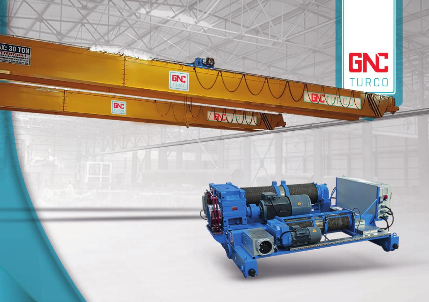
GNCDG Electric Wire Rope Hoist
An electric wire rope hoist family intended for overhead and gantry crane lifting applications.

Crane systems · Lifting technology · Tailored engineering
Crane systems, lifting technology and tailored engineering solutions for demanding industrial operations.
GNCTURCO develops crane and material-handling solutions around each facility’s workflow, geometry and operating conditions. Engineering, manufacturing coordination and export support are brought together in one disciplined process.
01Requirement-led engineering
02Clear technical communication
03Export-focused project coordination
Explore GNCTURCO crane systems by application. Product configuration remains subject to facility geometry, operating conditions and engineering review.
An electric wire rope hoist family intended for overhead and gantry crane lifting applications.

A rail-mounted lifting system for moving loads along a defined monorail path.

End-carriage assemblies for the travel motion of single-girder overhead crane bridges.

An overhead travelling crane arrangement intended for facilities with constrained headroom or suspended runway geometry.

End-carriage assemblies for underslung crane bridges operating below the runway structure.

An overhead crane configuration with two bridge girders supporting the lifting mechanism and travelling bridge.

End-carriage assemblies supporting the travel motion of double-girder overhead crane bridges.

A rail-travelling crane bridge supported by legs for outdoor yards or project-specific indoor applications.

Travel assemblies for gantry crane legs operating on the project runway system.
Official 28-page catalogue
Explore documented crane families, lifting components and selected reference projects in the official GNCTURCO catalogue.
Choose the closest system to begin a requirement brief. This step collects project information only; it does not provide engineering approval, product selection or a final price.
The existing FEM and ISO reference tables are retained below for accessible review. Final crane selection and duty classification require project-specific engineering verification.
Reference information only. These tables do not constitute project approval, capacity confirmation or a certification claim.
| Yılmaz Reduktor State of Loading | Km | Crane Classes (ISO 4301 / 1 • FEM 9.511 / 86) | ||||||||
|---|---|---|---|---|---|---|---|---|---|---|
| T0 | T1 | T2 | T3 | T4 | T5 | T6 | T7 | T8 | ||
| L1 - lıght | 0,125 | M1 (1Dm) | M2 (1Cm) | M2 (1Cm) | M3 (1Bm) | M4 (1Am) | M5 (2m) | M6 (3m) | M7 (4m) | M8 (5m) |
| L2 - MODERATE | 0,25 | M1 (1Dm) | M2 (1Cm) | M3 (1Bm) | M4 (1Am) | M5 (2m) | M6 (3m) | M7 (4m) | M7 (4m) | M8 (5m) |
| L3 - HEAVY | 0,50 | M1 (1Dm) | M2 (1Cm) | M3 (1Bm) | M4 (1Am) | M5 (2m) | M6 (3m) | M7 (4m) | M8 (5m) | — |
| L4 - VERY HEAVY | 1,00 | M2 (1Cm) | M3 (1Bm) | M4 (1Am) | M5 (2m) | M6 (3m) | M7 (4m) | M8 (5m) | — | — |
| Use based on the stress level (type of duty) | Tm = Average duration of daily operation (hours) | ≤ 2 | ≤ 4 | ≤ 8 | ≤ 16 | > 16 | > 16 | |
|---|---|---|---|---|---|---|---|---|
| Life span of the mechanisms in 10 years of operation (hours) | 3200 | 6300 | 12500 | 25000 | 50000 | 100000 | ||
| 1) Light | N° max of operating cycles in 10 years of operation (Σ cycles) | 250x10³ | 500x10³ | 100x10³ | 200x10³ | 400x10³ | > 4x10³ | |
| Tm = Average duration of daily operation (hours) | ≤ 1 | ≤ 2 | ≤ 4 | ≤ 8 | ≤ 16 | > 16 | ||
| 2) Medium | Life span of the mechanisms in 10 years of operation (hours) | 1600 | 3200 | 6300 | 12500 | 25000 | 50000 | |
| N° max of operating cycles in 10 years of operation (Σ cycles) | 125x10³ | 250x10³ | 500x10³ | 100x10³ | 200x10³ | 400x10³ | ||
| 3) Heavy | Tm = Average duration of daily operation (hours) | ≤ 0.5 | ≤ 1 | ≤ 2 | ≤ 4 | ≤ 8 | ≤ 16 | |
| Life span of the mechanisms in 10 years of operation (hours) | 800 | 1600 | 3200 | 6300 | 12500 | 25000 | ||
| 4) Heavy | N° max of operating cycles in 10 years of operation (Σ cycles) | 63x10³ | 125x10³ | 250x10³ | 500x10³ | 100x10³ | 200x10³ | |
| Tm = Average duration of daily operation (hours) | ≤ 0.25 | ≤ 0.5 | ≤ 1 | ≤ 2 | ≤ 4 | ≤ 8 | ||
| Life span of the mechanisms in 10 years of operation (hours) | 400 | 800 | 1600 | 3200 | 6300 | 12500 | ||
| N° max of operating cycles in 10 years of operation (Σ cycles) | 32x10³ | 63x10³ | 125x10³ | 250x10³ | 500x10³ | 100x10³ | ||
| Service group of lifting and travelling mechanisms | as per ISO standard 4301-1 | M3 | M4 | M5 | M6 | M7 | M8 | |
| as per FEM rule 9.511 | 1Bm | 1Am | 2m | 3m | 4m | 5m | ||
| Intermittent use as per FEDEM rule 9.683 | Hoist mechanisms | Ratio of intermittence (RI%) | 25 | 30 | 40 | 50 | 60 | 60 |
| Maximum n° of start-ups per hour (A/h) | 150 | 180 | 240 | 300 | 360 | 360 | ||
| Maximum n° of cycles per hour (C/h) | 25 | 30 | 40 | 50 | 60 | 60 | ||
| Ratio of intermittence (RI%) | 20 | 25 | 30 | 40 | 50 | 60 | ||
| Meccanismi del Carrello | Maximum n° of start-ups per hour (A/h) | 120 | 150 | 180 | 240 | 300 | > 360 | |
| Maximum n° of cycles per hour (C/h) | 20 | 25 | 30 | 40 | 50 | > 60 | ||
| Operation time at main speed (min) | 15 | 15 | 30 | 30 | 60 | > 60 | ||
| Operation time at low speed (min) | 2.5 | 3 | 3.5 | 4 | 5 | 6 | ||
| Max n° of start-ups per hour (A/h) | Maximum n° of start-ups per hour (A/h) | 10 | 10 | 10 | 10 | 10 | 10 | |
| High speed | 1/3 (33,3% of the total n° of start-ups per hour) | |||||||
| Low speed | 2/3 (66,7% of the total n° of start-ups per hour) | |||||||
| Tm = Average duration of daily operation (hours) | Main speed | 2/3 (66,7% of the average duration of daily operation) | ||||||
| Low speed | 1/3 (33,3% of the average duration of daily operation) | |||||||
Project-specific crane engineering for applications that cannot be served by a standard configuration.
Engineering in Motion
Scroll through a visual interpretation of how a lifting requirement advances from engineering to delivery.
Illustrative motion only — not an engineering simulation, lifting plan or safety calculation.
Requirements, geometry and operating context establish the technical brief.
Approved project information moves into coordinated fabrication and assembly.
Defined checks and documentation support the project-specific review process.
Equipment and documentation are prepared for the agreed logistics sequence.
A visual record of GNCTURCO equipment, assembly and dispatch preparation. Process details remain subject to project scope and technical review.

Project geometry and operating requirements establish the technical brief.

Components are prepared around the approved project documentation.

Mechanical and lifting elements are brought together for the defined system.

Equipment is prepared for the agreed logistics and installation sequence.
From requirement review to shipment coordination, GNCTURCO supports international industrial projects with clear documentation and direct technical communication.
Selected engineering work is presented separately from the product catalogue. Technical details are published only after project and media verification.

A reference project recorded in the existing website as a 100-ton redundant crane system manufactured in 2018.
Detailed project data will be published after engineering and media approval.
Share your capacity, span and lifting height. Our team will review your requirements and prepare a tailored solution.
Share the application, location and key dimensions. The GNCTURCO team will review your message and contact you about the next technical step.
LocationKonya, Türkiye


